Read case study
Designing for plastic injection moulding is like raising teenagers—some parts (and some teens) are more challenging than others. But by following a few simple rules, even the most difficult of these challenges can be overcome (parenting aside).
For injection moulding, there are some common troublemakers during part design:
Clips and snap fits Living hinges Bosses and stand offs Text on parts Overmoulding Look familiar? This list just happens to correspond with some of the more engaging features you can incorporate into your part designs, which is one reason why it’s so important to master them. Another is that, depending on your application, these features often provide more functional and aesthetic parts while reducing production costs. The following tips and techniques will help you do just that.
Clips and Snap Fits
There are plenty of examples where moulded parts need a clip or snap fit. The cover for an electronics device. A snap-on lid for a tool set. Both rely on a flexible, hook-like piece of material that extends into and catches on a female pocket or slot in the mating part. In either case, probably the best way to create these features is with a sliding shutoff, which as the name implies slides into the mould and prevents material from flowing into the desired area. This design also requires a hole in the part beneath the snap, the portion of the mould that passes through the part shutting off with mating features, which creates the snap fits.
However, this approach requires that the part feature is aligned with the direction of mould opening and that a relief hole at the base of the clip is allowable. Additional draft may also be required. If none of these are feasible, a side-action might be possible, but this must be aligned with the mould’s parting line and oriented perpendicular to the pull direction. Additionally, the side action must be accessible and remain in constant contact with the part.
Finally, hand-loaded inserts can be used. These are small chunks of machined metal that must be manually inserted and removed from the mould at each cycle. And consider the material—a flexible polymer-like ABS makes a better clip than does acrylic or PEEK, although some clever design tweaks such as adjusting the clip length or its geometry can get around many material constraints. Check with Protolabs’ applications engineers for other design tweak ideas (see customer service phone number and email address below).
Note: This whole discussion on clips applies equally well to any undercut or recessed part feature. This includes O-rings, side holes and pockets, windows, and so on. Based on the orientation of the part feature relative to the mould pull and parting line, various advanced moulding techniques such as side-actions, telescoping shutoffs, inserts, and pins might be needed. All are perfectly acceptable and well-understood solutions, although, due to the added complexity, some of these resolutions may have an effect on moulding and part cost.
Living Hinges
While we’re on the topic of lids and flexible materials, living hinges are a great way to keep the two halves of a moulded container together. Take a look at a vitamin dispenser or mint box—chances are good there’s a clip of some sort on one side and a living hinge on the other. The biggest consideration here is material. Where polycarbonate might make a good clip, it definitely won’t survive the thousands or millions of cycles expected of a living hinge. Shoot for polypropylene instead.
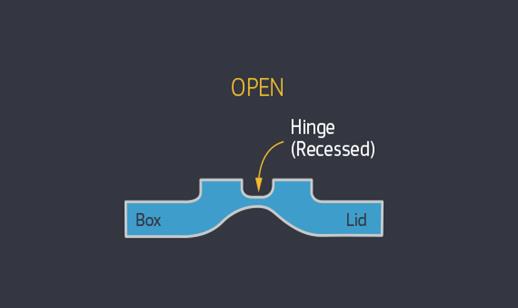
Breakaway tabs are similar to a living hinge. If you’ve ever peeled away the plastic cap on a refilled propane bottle or ice cream container, you know how they work. Whether tab or hinge though, some design accommodations must be made. The section should be thin enough to flex but thick enough to survive repeated bending. Depending on the expected range of motion, you might need a radius or groove at the midpoint of the hinge to allow it to fold over on itself. And because you’re attempting to mould two mating halves simultaneously and the material flow will likely be thick-to-thin-to-thick, flash and fill problems might occur. Be sure to pay close attention to the design for manufacturability (DFM) analysis you receive with your quote.
Bosses and Stand Offs
Not everyone likes the boss. But if you need somewhere to stick a threaded insert, a boss will certainly be necessary. Yet bosses, like tall ribs and thick standoffs, are potential problem areas. Additional draft up to 3 degrees or more might be needed to avoid ejection problems. Make any of these part features too thick and sink becomes an issue. The taller the feature, the deeper the mould must be, which means longer end mills and slower feedrates are needed to cut it. This also raises concerns for venting that may result in shorts, burning, or simply incomplete parts.
Some ways to avoid this include using vertical ribs or gussets around the periphery of the boss to support it, thus allowing thinner walls to be used. Be aware that Protolabs may need to place vent holes in deep (tall) ribs, standoffs, and bosses. And when angled, features such as this are a real pain in the neck because their axes diverge from both the direction of mould pull and the parting line, pretty much guaranteeing a hand-loaded insert will be needed.
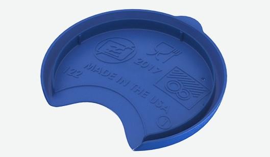
Text on Parts
Designing a product name or company logo on a part is a regular occurrence. But beware, this small detail can create big problems if approached incorrectly. For starters, tiny fonts are fine, but they should be a non-serif font (Arial or Century Gothic, for example) and the smallest stroke length—the cross bar on a T or A, or the legs on a K—must be at least 0.5mm across.
Raised rather than sunken text is both easier to create and more legible, and unless the text is very large—like the big print book your grandpa reads—should be no more than 0.38mm high (which means deep, as far as the mould is concerned). Text located down inside a pocket might be tough to reach with an end mill—any chance you can place it somewhere closer to the parting line or away from tall standing features in the mould? And unless you’re moulding a squishy material like liquid silicone rubber (LSR) or thermoplastic elastomer (TPE), the text should always face the direction of mould pull, else part ejection can be problematic and we would need to incorporate hand-loaded inserts or side actions.
Overmolding
Rapid overmoulding is a great way to add an ergonomic grip to a screwdriver handle, a no-slip, sanitary grip to a surgical device, and an impact resistant shell to an instrument housing. There’s no longer a need to glue or screw these coverings to your injection-moulded part, because overmoulding accomplished it in a two-step process that provides far better adhesion than traditional bonding methods.
It works by placing a previously moulded part into a secondary mould and then shooting it with overmould material. There are some things to be aware of, however. The two materials should be compatible—thermoplastic polyurethane (TPU) over ABS or polycarbonate make good partners, as do TPE and some polypropylenes. LSR is also a desirable overmould material, but its moulding temperature is high enough to bake a casserole (around 177 degrees C), so the substrate must be able to handle the heat. Glass-filled nylon is one good option.
The type of bond should also be considered. Each of the examples listed provide a secure chemical bond, but some materials are not so compatible and must be mechanically bonded. By now you might be leery of undercuts on your injection-moulded parts but this is actually an effective way to assure a no-fail mechanical interlock on overmoulded parts. Regardless of the materials under consideration, most polymer manufacturers recommend a double whammy of chemical and mechanical bonding. It’s also a good idea to speak with the overmoulding material supplier before embarking on any large scale project. That’s something a Protolabs applications engineer can also help you with.
Along those lines, as always, feel free to contact Protolabs with any questions, on +44 (0) 1952 683 047 or customerservice@protolabs.co.uk. To get your next design project started today, simply upload a 3D CAD model at protolabs.co.uk for an interactive quote within hours.