5.0 Damping
In addition to providing lubrication for the seals, piston and piston rod oil contained within a gas spring also provides velocity control for the spring at the end of its extension stroke.
The oil acts to slow the spring and prevents shock loadings as it reaches full extension. Without this damping control, rapid control extension of the gas spring would occur that could result in product failure, damage or injury.
Damping is usually achieved by regulating the flow of gas and oil through the piston. When mounted in the preferred rod down position, maximum damping is achieved once the piston reaches the internal column of oil near the point of full extension.
This is referred to as the oil damping zone; the effect on the velocity of the spring is shown in figure one below:
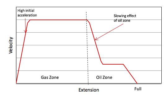
Figure One: Effect on Velocity of the Spring
The level of damping can be influenced by several factors which include:
- Operating temperature
- Oil viscosity
- The relationship between the tube and rod diameters
- The volume of oil
- Pour point of oil
Looking at these factors in greater detail:
Operating Temperature
Operating temperature affects damping in two ways:.
- As the temperature increases, the force within the spring increases (as explained in detail in Technical Guide Edition 1.1).
- The oil will reduce in viscosity.
As a consequence, the spring will extend faster and have less damping.
In lower temperatures the opposite will occur, with extension force reducing and oil viscosity increasing; thus, the spring will extend at a slower rate and have higher damping.
Oil Viscosity
Viscosity, by definition, is a fluid’s resistance to flow and shear.
Oil is a high viscosity fluid. As temperature increases, the viscosity of the oil reduces, meaning it will flow faster and have less resistance to objects passing through it (such as the piston or gas spring).
Oils can be specified with differing viscosities (resistance to flow) with the higher the viscosity number indicating the higher the resistance.
Viscosity is primarily determined by the length of the molecule structure of the oil, with the longer the molecule chain, resulting in a thicker (or higher) viscosity oil.
The higher the viscosity of the oil, the greater the damping effect will be on the gas spring.
However, a further factor to take into consideration is the Viscosity Index of the oil. This indicates the rate of change between two temperatures.
The rate at which viscosity changes is non-linear and viscosity charts are plotted as a logarithmic function against linear temperature.
Higher viscosity oils tend to have a higher Viscosity Index. This indicates they are subject to greater levels of viscosity change than a lower viscosity oil.
The result on the gas spring will be a more pronounced change in damping behaviour with temperature fluctuations.
The Relationship Between Rod and Tube Diameter
The greater the tube diameter relative to rod diameter, the greater the volume of fluid which is required to pass through the piston (and subsequently the greater the damping effect will be).
Thus, an 8-23 spring will exhibit a higher level of damping than an 8-18 or 10-23 using the same oil type and level.
If consistent damping is required over the entire stroke to achieve a controlled rate of extension or compression, then fully fluid dampers should be used.
Oil Volume
The higher the volume of oil contained within the spring, then the earlier the gas spring will hit the oil damping zone and the slower the extension speed will be.
Pour Point of Oil
The pour point of a liquid is the temperature at which it becomes semi-solid and loses its flow characteristics.
For a gas spring, this means that once the pour point is reached, the oil effectively becomes a solid. The full stroke of the gas spring cannot be fully utilised, and no damping will occur.
6.0 Metering and Extension Speeds
Metering
Metering controls the rate of extension and/or compression of a gas spring.
Different manufacturer’s use different techniques to achieve this. From altering piston orifice sizes to creating restrictive flow paths through the piston.
Fundamentally, whichever method is used, the purpose remains to create a pressure drop across the piston to control the rate of extension.
The larger the piston orifice, or shorter the flow path the less the pressure drop, the less restricted the flow path and the faster the spring will extend.
7.0 Friction and P1-P4 Charts
Without friction, the force/displacement curve for a gas spring would follow a straight line as shown in figure two below.
In accordance with Boyle’s Law, the force would increase as the rod is pushed into the tube and it would return along the same line as it extended.
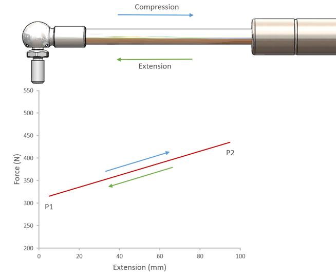
Figure Two: Force/Displacement without Friction
However, friction is present in every gas spring and friction opposes motion.
Due to friction, the force required to compress the spring increases above the theoretical force output as it is compressed, whilst decreasing the output force as it extends.
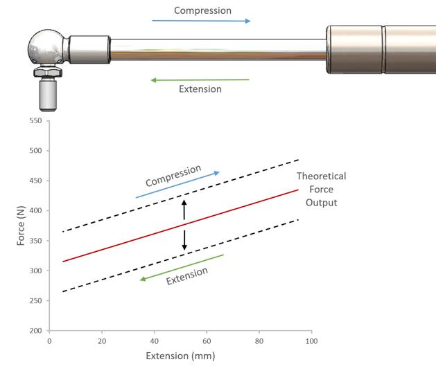
Figure Three: Force/Displacement with Friction
This can be further developed into the idealised P1-P4 force/displacement curve (P1-P4 chart) shown in figure four.
This is the industry standard format for gas spring manufacturers.
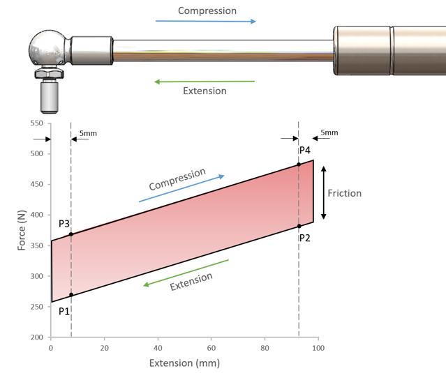
Figure Four: Idealised P1-P4 Force/Displacement Graph
As previously noted, friction is present in every gas spring with the amount affected by several factors:
- It increases as the internal pressure increases.
- It increases the faster the rod extends.
- It will increase the longer the spring is allowed to sit at rest (breakaway friction)
- It is affected by the surface finish of the rod/tube and the materials used.
There are four standard positions where a gas spring manufacturer will measure a springs force. These are referred to as the P1 to P4 points:
- P1 – This is the measurement 5mm from full extension in the extending direction.
- P2 – 5mm from full compression into the extension stroke, the resultant force decreases to point P1 as the rod extends and the available gas volume increases.
- P3 – 5mm from full extension into the compression stroke, the force is greater than at the P1 position because of friction.
- P4 – 5mm from full compression in the compression direction. The measurement of force increases from the P3 position as the rod is compressed and the available gas volume decreases.
- P1 Static – This is the nominal force of a gas spring. To measure this force, the spring is compressed 10mm then allowed to extend 5mm and held. This is the industry standard position for a gas spring force output.
- The difference between P3 and P1 values is the dynamic friction. The same is true for the difference between P4 and P2.
A further factor affecting spring performance is breakaway friction (also referred to as stiction).
This occurs when a spring has been allowed to remain stationary for a period of time; this can be as little as a few hours.
Because of the pressure contained within the spring, the tendency is for the lubrication to migrate away from the seals and the rubber is forced into the minute cracks and crevices within the metal.
When the spring is cycled for the first time, additional force is required to overcome both friction and to free the rubber from the cracks and crevices. This is illustrated in figure five.
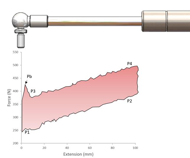
Figure Five: Effect of Breakaway Friction (Pb) on P1-P4 Chart
The measurement Pb is the breakaway force and shows the effect of stiction over and above the idealised P3 force shown in the Idealised P1-P4 Force/Displacement Graph (figure four).
On subsequent cycles, stiction is significantly reduced and dynamic friction is also reduced to the lubricating effects of the oil. This is illustrated in figure six.
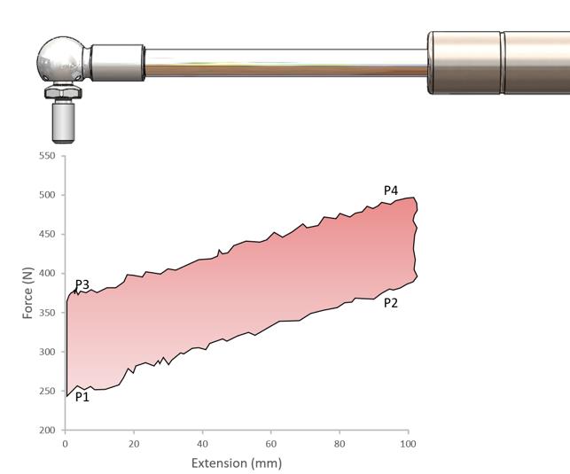
Figure Six: P1-P4 Chart Following Initial Breakaway
A typical Camloc P1-P4 chart can be seen in figure seven. This shows the stiction and friction effects previously described.
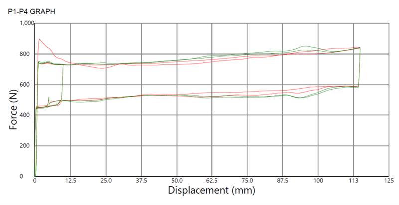
Figure Seven: Typical Camloc P1-P4 Chart
The chart illustrates the following:
Cycle One (Red Line) – This is the first cycle of the spring which allows for measuring the breakaway force.
Cycle Two (Green Line) – This is used to dynamically measure the P1 to P4 points of the spring.
Cycle Three (Green Line) – This will follow the line created in cycle two, but here the static P1 force is required.
8.0 Force and Force Ratio’s
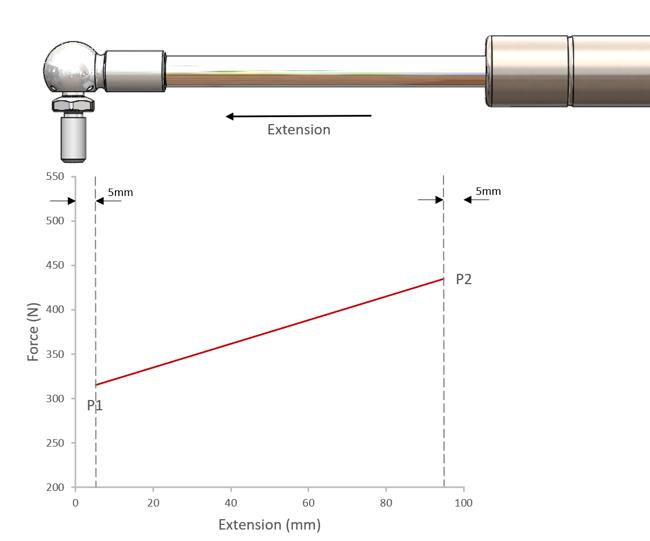
Figure Eight: Force Ratio (K-Factor or Spring Rate)?
Force Ratios
As a gas spring extends from P2 to P1, there will be a change in the output force of the spring. This is called the ‘force ratio’ (alternatively K-Factor or Spring Rate).
This is the relationship between the final compressed force (P2) and the charge force (P1) of the spring, being expressed as P2/P1. This ratio describes the rate of change of force, with the higher the value, the greater the change in force.
Force ratios tend to increase as the outside diameter of the spring increases. Typical values for force ratios are given in figure nine.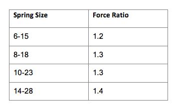
Figure Nine: Typical Values for Force Ratios
Using an example of 6mm and 10mm diameter rods charged to 40bar, with P1 forces of 315N and 113N respectively; the resulting P2 forces would be 436N and 148N (both minimum tube lengths, internals and 10mm oil level); the resulting force ratios would be 1.38 for the 10-23 spring and 1.31 for the 6-15 spring.
Figure ten shows force ratios for a range of standard size springs, each charged to 40bar.
It can be seen from this chart how the force ratio increases with diameter of the gas spring.
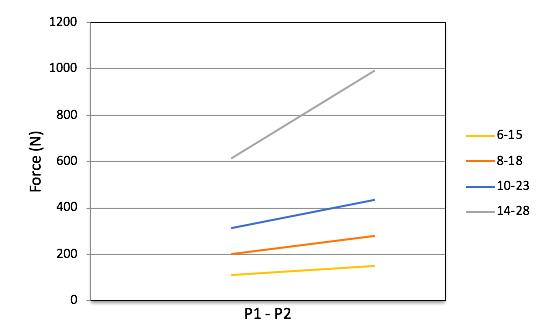
Figure Ten: Force Ratios for Standard Size Gas Springs
Using Force Ratios to Optimise an Application
Force ratios allow for optimisation of a gas springs performance to suit the application.
Low force ratios (typically small diameter springs) are useful on applications such as straight vertical lifts (e.g. machine guards) or top-hinged vertical access panels where it is desirable to have the extended and compressed forces almost equal.
High force rations (usually larger diameter springs) are useful when a higher P2 force is preferable in relation to the P1 force. Such an application might be a horizontal cover opening to 90 degrees where a high force is required to assist in the initial opening and little force is required to maintain the cover in a 90-degree position.
It is possible to change force ratios by:
- Minimising the length of the tube used relative to the stroke to increase the force ratio.
- Reducing the diameter of the tube increases the force ratio (for the same diameter rod).
- Increasing the diameter of the rod increases the force ratio (for the same diameter tube).
- Increasing the used stroke increases the force ratio.
- Increasing the oil level increases the force ratio.
All the above affect the relationship between the volume of gas in the cylinder and the amount of gas displaced as the spring is compressed.
It is important to ensure that factors of safety for tube burst pressure are considered when force ratios are altered.
9.0 Oil Levels
The primary reason to use oil in a gas spring is to provide lubrication to the seal and prevent damage caused by friction between the seal and the piston rod.
The secondary function of the oil is to act as the damping medium for the spring.
A common requested requirement is to increase the damping of the spring which would normally be achieved by increasing the oil level, but what are the implications of doing this?
- It will increase the P2 force of the spring.
- It may alter the handling characteristics of the application (P2/P1 force ratio)
- In some cases, it may increase the P2 pressure above safe limits.
Why does the P2 force increase?
The P2 force increases due to replacing a volume of compressible gas (Nitrogen) with an incompressible fluid (oil).
The remaining gas has less available volume and therefore it is subject to greater compression as the rod is inserted.
How is the handling characteristics (P2/P1 force ratio) altered?
Adding oil may be desirable in some applications, a good example being a horizontal cover opening to 90 degrees vertical where a high force is required to assist in the initial opening and a low force is required to maintain the cover open in the 90 degree position,
Conversely, if the handling forces are sufficient but a request is made for more damping, what is likely to happen?
Firstly, because of the increased P2 force the self-rise angle will be reduced; the spring will accelerate the application more rapidly during the initial opening and it will be more difficult to close the application due to the higher P4 force generated.
To demonstrate this using the 10mm rod example with a P1 force of 315N (P2 of 437N), a stroke of 100mm and using 40mm of oil instead of 10mm; the P2 force would increase to 540N
This increases the P2/P1 force ratio from 1.38 to 1.71, as can be seen in figure eleven.
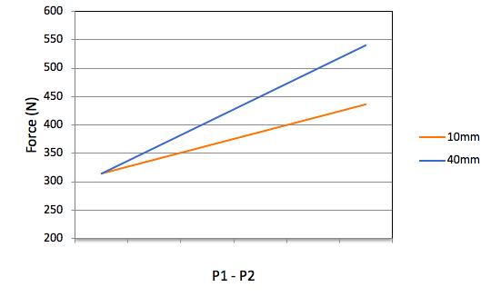
Figure Eleven: P2/P1 Force Ratio with 40mm and 10mm of Oil
Why can the P2 pressure increase above safe limits?
Camloc gas springs are sized to ensure that the effects of force, oil level and temperature remain within acceptable factors of safety.
In some cases, the spring could have a long stroke relative to the tube length, high force, maximum oil levels and used at elevated temperatures; by adding more oil, may take the P2 force above safe limits.
Camloc would never recommend increasing the oil level if this were the case.