1.0 Technical: Forces
A gas spring is defined by its force output in the extending direction; this is referred to as the P1 force.
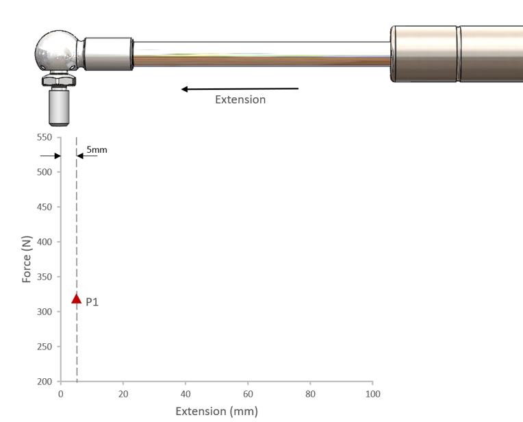
Figure One: P1 Force
The P1 force is the static force measurement taken 5mm from full extension in the extending direction.
The units of measurement are Newtons; this is the industry standard measurement for force output.
Force output is a function of the charge pressure in the cylinder acting on the cross-sectional area of the rod. Mathematically this is described by the equation:
Force = Pressure x Area
Consequently, the larger the diameter of the rod and therefore rod area, the greater the force output will be for the same charge pressure.
Worked Example
What is the P1 force of a 10-23 spring charged to 40 bar (4MPa)?
The rod diameter is 10mm, so the radius of the rod in SI units is 0.005m
P1 = p x A
P1 = 4MPa x (π x 0.0052)
P1 = 315N
How is the static P1 force measured?
To measure the static P1 force the gas spring is compressed to 10mm from full extension; the spring is then allowed to extend to 5mm from full extension and dwell for five seconds prior to the P1 static value being taken.
Charge Pressures
Camloc Gas Springs are charged with Nitrogen at pressures between 15 and 200bar (1.5 to 20MPa).
Settleback
Due to how Nitrogen is injected into the gas spring the internal pressure of the spring will reduce immediately after gassing.
Typically, this will be around 5% in the first 24 hours; being termed as “settleback”.
2.0 The Effect of Rod Diameter
As described in section 1.0, the output force of a gas spring is a function of the charge pressure acting on the cross-sectional area of the rod, described by the equation:
Force = Pressure x Area
As a result, the larger the diameter of the rod (therefore the area), the higher the output force will be for the same charge pressure.
A gas spring extends due to the difference in pressures acting on the cross-sectional area of the rod, it is the only factor that affects the P1 output force.
The diameter of the tube is immaterial to the P1 force generated.
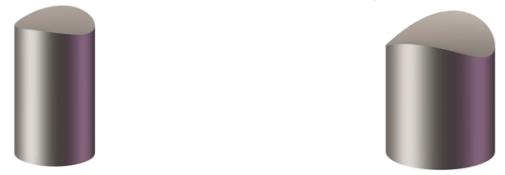
Figure Two: 6mm Diameter Rod (Left) & 10mm Diameter Rod (Right)
Taking a practical example, the cross-sectional area of a 6mm rod is 28.3mm²; whereas, for a 10mm rod, this is 78.5mm². An increase of 177%.
This increase in cross-sectional area explains why the force range of a spring increases as the rod diameter increases.
Worked Example
Using the example from section 1.0, a spring with a 10mm rod charged to a pressure of 40 bar (4MPa) will yield a P1 force of 315N.
P1 = p x A
P1 = 4MPa x (π x 0.0052)
P1 = 315N
Whereas a spring with a 6mm rod charged to the same pressure will yield a P1 force of only 113N.
P1 = p x A
P1 = 4MPa x (π x 0.0032)
P1 = 113N
Although the pressure remained identical, the area being acted upon has reduced, thus the force output is also reduced.
3.0 The Effect of Rod Insertion
The force output of a spring is greater in its compressed state than in its extended state, this is due to ‘rod insertion’.
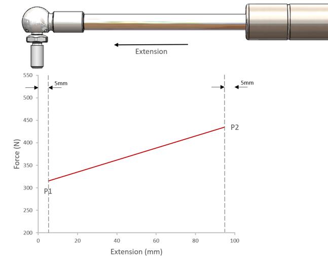
Figure Three: Effects of Rod Insertion
As described in section 1.0, the P1 value is the force measurement in the extending direction taken 5mm from full extension.
Similarly, the P2 value is the force measurement in the extending direction taken 5mm from full compression.
The P2 value will always be greater than the P1 value as explained by Boyle’s Law.
Boyle’s Law is a basic law of chemistry which describes the behaviour of a gas held at a constant temperature. The law states that at a fixed temperature, the volume of the gas is inversely proportional to the pressure exerted by the gas.
Gas springs are sealed units so, in accordance with Boyle’s Law, when a force acts upon the rod and pushes it into the cylinder compressing the spring – the available volume for the gas is reduced due to the volume displaced by the rod.
As a result, the internal pressure (and consequently the force) increases, mathematically described by the following formula:
p1 x V1 = p2 X V2
It should be noted that the piston has no effect on compression. It only determines the rate at which the spring is compressed or extended.
The volume of oil contained within the spring must be taken into consideration when calculating the P2 force. Oil is considered an incompressible fluid and will reduce the available volume for the gas within the spring.
For the purposes of calculating the P2 value, we ignore any effects of friction (which is discussed in greater detail in edition 1.2).
The rate of climb in force between P2 and P1 is referred to as the ‘force ratio’ (sometimes referred to as the ‘k’ value and further explained in edition 1.2).
Volume displaced by rod insertion is illustrated in figure four:
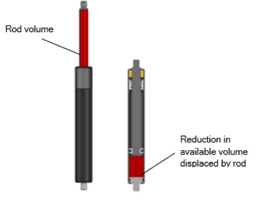
Figure Four: Rod Insertion Displacement
Worked Example
Taking the previous example of the 10-23 spring charged to 40bar with a P1 force as being 315N; if the total stroke is 100mm and the spring is filled with 10mm of oil, what would the force be?
In addition, what would the P2/p1 force ratio be?
To calculate volume, V1:
V1 = (π × piston radius2) × (stroke - oil level)
V1 = (π x 0.012 × (0.1 - 0.01
V1 = 0.0000283m3 (28.3x10⁻⁶m3)
To calculate volume, V2
V2 = v1 – (rod area x stroke used)
V2 = 0.0000283 – (π × 0.0052 × 0.1)
V2 = 0.0000204m3 (20.4x10⁻⁶m3)
To calculate pressure, P2
P2 = P1 x V1/V2 = 315 × V1/20.4x10-6
P2 = 437N
To calculate the Force Ratio, k
k = P2/P1 = 437/315
k = 1.38
4.0 The Effects and Limits of Temperature on Gas Springs
Temperature affects the performance of a gas spring in two ways; it varies the force output, and it increases the susceptibility to gas loss.
What is the effect on output force?
It’s accepted that the output force of a gas spring varies with temperature. At low temperatures the force will reduce, whilst at high temperatures it will increase.
This is described by Charles’ Law, which defines how (at constant pressure) a gas will expand as the temperature increases.
in the case of a gas spring, the volume remains constant due to it being physically constrained within the body of the spring and therefore as the temperature increases the pressure within the spring increases.
This is described by the equation:
P1/T1 = P2/T2
Where:
- P1 = Initial pressure (or this can be substituted for force)
- P2 = Final pressure (or again this can be substituted for force)
- T1 = Initial temperature
- T2 = Final temperature
The equation shows that for a fixed volume, as absolute temperature increases, the pressure of the gas increases proportionally.
It should be noted that because Charles’ Law is a gas law, all temperatures must be expressed in units of absolute temperature i.e. Kelvin. This is the temperature in degrees Celsius plus 273.15.
Worked Example
If the force of a spring is 1000N at 20°C, what would the forces be at -40°C and at 80°C?
Re-arranging the above equation we get:
P2 = P1/T1 × T2
Therefore, at -40°C:
P2 =1000/293.15 × 233.15 = 795N
Whilst at 80°C:
P2 = 1000/293.15 × 353.15 = 1205N
The effect of temperature change for this spring is shown in figure five:
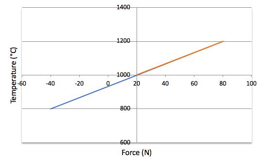
Figure Five: Effect of Temperature Change
Important – Unless otherwise stated, gas spring application will be sized at 20°C. For this reason, it is important to understand the operating temperatures of an application as it can make a significant difference to the handling characteristics in the real-world environment.
Why does the gas spring become susceptible to gas loss?
In addition to the effect on force output, extremes of temperature affect a gas springs ability to retain its charge.
At high temperature, the softness of the rubber used for the seals increases and consequently so does the permeability of the rubber. This allows the gas molecules to escape through the seal more easily.
On the other hand, at very low temperatures the rubber compounds stiffen; this also allows gas loss.
Camloc Gas Springs
Gas springs manufactured by Camloc are set at a nominal temperature of 20°C and will vary by approximately 0.3% of nominal force per °C of temperature change.
The viscosity of the oil used for damping is also affected by temperature and this will result in changes to the damping.
Standard gas springs are rated for use between -20°C and +80°C.
Special gas springs can be manufactured for use between -40°C and +100°C.
Camloc use the “temperature compensation” spread sheet to calculate the effect of temperatures.