Additive manufacturing (3D printing) is unique in its ability to produce parts with lattice or mesh structures. These lattices are a versatile tool for engineers for several reasons. Lattice structures help make parts lighter and stronger. They can also help reduce part volume, which leads to fewer surface defects and prevents excessive stress buildup. Less volume has the added benefit of saving on build time, and therefore cost. The additional surface area of lattice structures can also be used in heat transfer applications. Read on to learn how to use lattice structures in your 3D-printed parts without making a mesh of things!
Lattice Structures Dependent on Technology
With the technologies we offer in-house the parts are built surrounded by raw material, whether it is resin or powder. Consequently, lattice structures can’t be completely enclosed. The parts will need access holes so that the raw material can be fully removed. This is in contrast to fused deposition modelling (FDM)—a filament based additive technology—where parts are surrounded by air during the build, allowing enclosure of the internal lattice by the outer walls of the part.
Using lattice structures while using more advanced resin- and powder-based 3D printing technologies is still a reality with a few considerations.
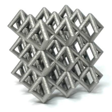
Adding a lattice to your part’s internal structure improves structural integrity and done right, can make your parts more lightweight.
Additive Technologies with Support Structures
Stereolithography (SLA) is a resin-based technology that requires supports when printing. For resin-based technologies, we prefer having a few drain holes to allow us to rinse the uncured resin out of the part prior to the UV post-cure. If any uncured resin remains, it will solidify during the post cure process. If the lattice needs to be completely enclosed, we can add drain holes for the build and part cleaning, and then plug the holes before shipping. You can use the Special Instructions field in your quote to request that we add drain holes and plugs and let us know if you have a preferred location for these features.
Direct metal laser sintering (DMLS) is a powder-based technology for metal that also requires support structures. Unlike our powder-based plastics, the metal powder is not caked onto the parts. The powder flows freely, like sand, making it much easier to clean out internal cavities. We also have a powder-removal machine that shakes and vibrates parts to get powder out of complex internal channels. However, any powder that remains inside the part will solidify during the stress relief cycle. If a channel or cavity needs to be clear, make sure there are plenty of places for powder to drain.
Support-Free Additive Technologies
Selective laser sintering (SLS) and Multi Jet Fusion (MJF) use powder-based plastic materials. Both rely on partially sintered or partially fused powder to support the parts during the build, removing the need for additional support structures. This means that the powder surrounding the parts is caked on like dried mud. We use compressed air to remove the powder after the build. However, we require a direct line of sight to the powder to effectively clear it out. While the air will eddy around the inside of the cavity, only the powder directly in front of the air nozzle will be removed. Because of this, lattice structures for SLS and MJF should be designed with plenty of access points for clearing powder.
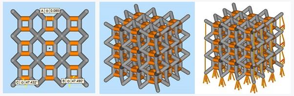
Below are examples of parts with increasing access to clean out the partially sintered/fused powder. The first example, on the far left, allows very little powder to be removed. Powder will be cleared in the area around the opening, but far corners of the part will be filled with powder. The middle example is better, there is significantly more access to blow out the powder. However, some powder may remain in the very back of the part in areas that are the hardest to reach. The last example, on the right, is ideal; there is plenty of access to remove powder and we can approach powder removal from both sides.
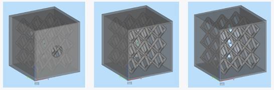
It's important to add design elements that allow removal of excess powder from your parts. The rightmost example does it best.
How to Design Your Lattice
Any models we receive are built 100% solid, unless we have a concern about warp; we don’t apply infill before building. We ask that any lattice structure be modelled into the part before it's uploaded to our site. Below are guidelines on how to design lattice structures that won’t trap raw material or require inaccessible supports.
The two main obstacles for a self-supporting lattice are bridge distances and angle from the build plate. SLS and MJF have the most design freedom when it comes to support structure. The ideal lattice for this technology is relatively open so that there is plenty of access to blow out un-sintered/un-fused powder.
Since SLA can span much larger distances without requiring supports, most lattice designs will be self-supporting. If the lattice needs to be entirely enclosed, we can add drain holes to the part for the build, and then plug them with the same material after removing the uncured resin from the inside. If you’d like to go this route, you can request it via the Special Instructions field in your quote and let us know on which surfaces you’d like the plugs.
DMLS is the most challenging technology for which to design lattice structures, as it can only span about 0.079 in. (2mm) before requiring supports. Bridge distances and self-supporting angles play a much bigger role in avoiding supports inside a lattice.
| | Guidelines for Self-Supporting Features |
| | Max Bridge | Min Angle (Deg) | Recommended Lattice Member Thickness |
| SLA | 7mm | 45 | 0.8mm |
| DMLS | 2mm | 45*
55 for 316L | 0.8mm High Res 1.3mm Normal Res |
| SLS and MJF | n/a | n/a | 3.2mm |
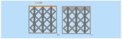
The following six examples feature different types of lattices. Each of these would be self-supporting in SLA due to short bridge distances. However, only some of these examples would be self-supporting in DMLS. Read on to see which lattices need supports in DMLS and why. Orange features indicate areas that require a support structure. It is important to note that while we may be able to remove support structures on the outer edges of a lattice, we will not be able to remove them in the center of the lattice.
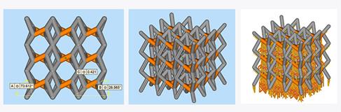
When Does Bridge Length Require Supports?
In both of these cases, the highlighted areas need support because the bridge distance exceeds 2mm. Proper supports are visible in the rightmost versions of each part.
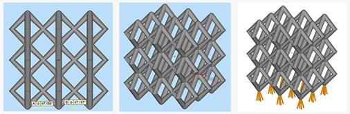
Working with Overhangs and Support Structures
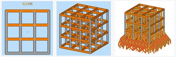
The highlighted areas need supports because they grow as overhangs at an angle less than 45 degrees to the build plate. These are considered overhangs, not bridges, because each side connects back to the part at a different Z-height. The other members do not require supports because they grow in at a high angle.
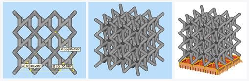
High Angles Help Simplify Lattice Structures
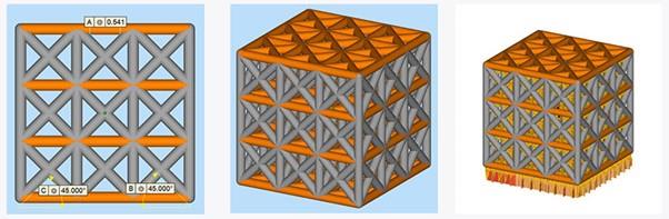
The lattice examples below are self-supporting because all features grow at an angle ≥45 degrees.
Ensuring Your Lattice Ends with Strength
The edges of the lattice also need consideration because they ensure part integrity. Even a self-supporting lattice may require some support structures where it meets a solid section of the part. The lattice pictured to the left is self-supporting. However, when the roof of the part comes in, the bridge distance is too long, and these areas will require supports.
One way to avoid support structures is to make the area between the top of the lattice and the wall of the part solid, as shown below on the right. Alternatively, if some support structures are acceptable, we can build the part as is.
If the lattice structure doesn’t end in a wall, as in the example above, the lattice should end as neatly as possible. In the example below, the left side of the lattice ends in such a way that some features will need supports. The image on the left shows a cross section representing what this part will look like as it grows in. Notice there are four islands, in orange, that grow in floating, as opposed to growing off an existing feature. Any features that grow in like this will require supports. The orange boxes in the picture on the right show where supports will be on this part if built as is. While these supports will be accessible, there is a risk that the fine lattice features could bend or break as part of the support removal process. Ideally the lattice would end in a way that avoids these islands, as with the right edge of the image below.

Gyroid Lattice
Gyroid lattices are more complex but offer unique benefits. They have nearly isotropic properties and a good ratio of strength to lattice density. This means that using gyroid lattices can lead to reduction in material volume, build time, and cost. However, these are trickier to implement without causing issues such as trapped supports or powder.
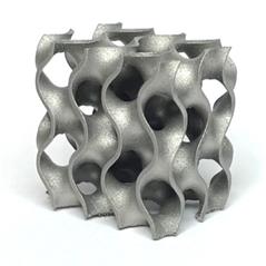
Gyroid lattices provide unusually strong internal support for printed parts.
Technologies with Support Structures
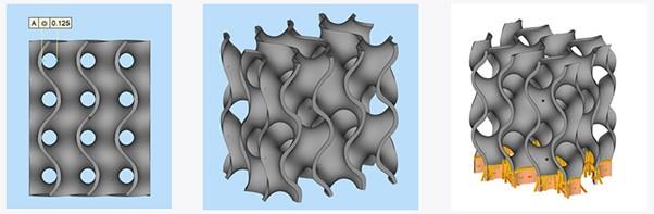
For SLA and DMLS, the first hurdle is avoiding internal supports. When viewed from the side, you can think of gyroid lattices as channels where the walls are cut away. To avoid internal supports on the inside of the lattice, the diameter of the channel should be within the maximum diameter for self-supporting channels.
| | Max Unsupported Channel |
| SLA | 25mm |
| DMLS | 6mm |
| SLS and MJF | n/a |
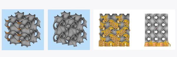
With a gyroid lattice, file resolution is also important. If the file resolution is low and there are a lot of coarse facets, the faceting can cause sharp artifacts that will grow in as islands and require supports. In the first two examples below, the file resolution is sufficient. However, in the last example, the file resolution is very low and it’s likely that the sharper angles may cause supports to grow somewhere inside the lattice. With gyroids, the complexity makes it difficult to manually comb through the file and identify areas that require supports that don’t have them. The lower the resolution of the file, the larger the chance of under-supported areas causing build issues.
On the other hand, if the file resolution is too high, the file size will be extremely large and may be difficult to prep and to slice. Therefore, gyroid lattices work best for small parts or small sections of parts so that the file size does not exceed what our prep and slicing software can handle. Check out this design tip for more information on STL file resolution.
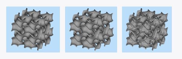
Examples of gyroid structures and how resolution affects the build.
Support-Free Technologies
For our support-free technologies, SLS and MJF, the ideal gyroid lattice would be low density. Since we need a line of sight to all areas to completely clear the powder, any gyroid lattice will be a challenge for powder removal and there will be risk of some powder remaining. That said, the more dense the lattice, the more residual powder.
Channel Diameter and Support Structures
In this first example, the entire lattice requires supports in DMLS because the channel diameter is larger than 0.236 in. (6.00mm).
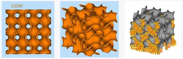
This lattice, however, is self-supporting because the channel diameter is smaller than 0.236 in. (6.00mm).
Ensuring Gyroid Lattices End Properly
As with other types of lattices, how the gyroid lattice ends can make or break the success of the build. Ideally, a gyroid lattice should be surrounded by solid walls so that as it grows; it does not terminate in a feature that will require support structures. The part on the left side below has the lattice surrounded by walls on all four sides, which will help support the lattice. The second part has the lattice ending without support from a solid wall. Since the lattice on the second part ends with shallow angles, the edges of the lattices will need support structures that we may not be able to remove.
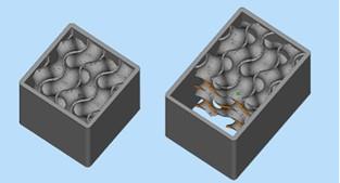
Gyroid structural integrity is all about proper endings.
If the lattice must end without a solid wall, it should end such that the edges are self-supporting. The first picture below shows one side of the lattice ending in places with low-angled walls that will require support structures. On the other hand, the lattice in the second picture ends such that all the angles are 45 degrees or higher from the build plate. The second lattice will require no supports and will build more successfully.
Additional Resources
If you need further assistance the following resources are available:
- Book an appointment to discuss your design with one of our Application Engineers
Schedule a Free Design Review
Alternatively, please