Designing excellent injection-moulded parts is dependent on many factors. Proper flow of the resin into the mould is one of them. We digitally simulate resin flow through your part geometry during our DFM (Design for Manufacturability) analysis. The resulting data that emerges will essentially help you design a part that will mould better.
Resin flow analysis is automatically applied to a small percentage of parts where mouldability issues are immediately present, but flow analysis is also available upon request. Better yet, it’s free, all to help you design better parts and help us get them to you as fast as possible.

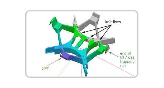
Figure 1: Flow analysis helps determine gate placement, locate knit lines and identify areas where gas trappings can occur. If needed, Application Engineers (AEs) can recommend design modifications to improve the mouldability of the part.
How does resin flow analysis help?
- It aids in the positioning of the gate or gates on your part.
- It shows the position of knit lines allowing you to improve the cosmetic and physical properties of your part (Figure 1).
- It locates trouble spots that are hard to fill within the part.
- It tells you whether or not we can fill your part with a selected material.

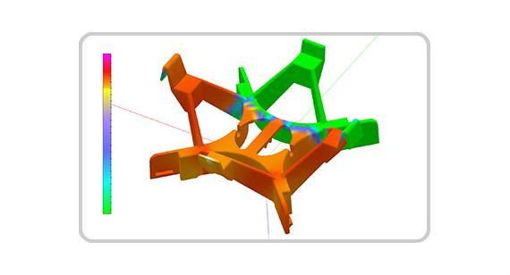
Figure 2: The colour coding gets “hotter” as the pressure increases. Gold, yellow and red represent high pressure and reduced flow. Blue and green colours mean flow is good, and the part will have a wide process window to work with.
The analysis also examines how resins flow with specific temperatures and injection pressures (Figure 2). As the material cools, it begins to harden, so gate pressure increases. The higher the pressure, the more complex the fill, which creates more significant concern about weak knit lines (contributing to poor part integrity), flash, sink, and shorts.
Plastics with good flow characteristics include polypropylene, K-Resin, HDPE, LDPE and unfilled nylons. Resins such as PC and ABS/polycarbonate tend to flow poorly.
Resin flow analysis works to pinpoint issues that can arise from these difficult flowing materials as well as other issues like thin walls and complicated geometries, providing solutions to improve flow and mouldability. Our design analysis, however, does not show areas of distortions or sink in your part.

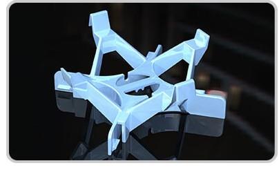
Figure 3: With the help of resin flow analysis, slight modifications such as increasing wall thickness can be made to your CAD model to create better flow and, ultimately, better parts.
If a material is not listed, our Application Engineers (AEs) will run an initial flow analysis with our default material, Makrolon 2458 (PC). Since it’s a difficult resin, a successful run-through resin flow analysis often means that any other resins you select will also work.
What if your part is not filling right? An AE can provide solutions such as increasing the wall thickness of the part, adding multiple gates or different material options (Figure 3). Remember that if you see Makrolon 2458 listed as the material and it’s not what you intend to use, AEs can correct it and run another simulation.
For additional resources such as moulding and prototyping processes, resin options, video tutorials, and more, check out protolabs.com/en-gb/.
As always, feel free to contact an applications engineer with any questions, at applicationengineers@protolabs.co.uk or contact our customer service department at customerservice@protolabs.co.uk
